Home>>NEWS>>Industry News>>CNC Machining vs. Laser Cutting: Choosing the Right Process

CNC Machining vs. Laser Cutting: Choosing the Right Process

2025-05-07
In modern manufacturing, Computer Numerical Control (CNC) machining and laser cutting are pivotal technologies, enabling the precise and efficient production of components across industries like aerospace, automotive, medical, and electronics. While both rely on digital control, they operate on fundamentally different principles. CNC machining is a subtractive process, carving material from a solid block. Laser cutting uses a focused light beam for thermal separation, melting, burning, or vaporizing material. This core difference dictates their unique capabilities and limitations, making the choice between them a critical decision based on material, design complexity, precision needs, volume, and budget. This guide provides a concise comparison to help you select the most effective process.

Understanding CNC Machining

The Subtractive Method

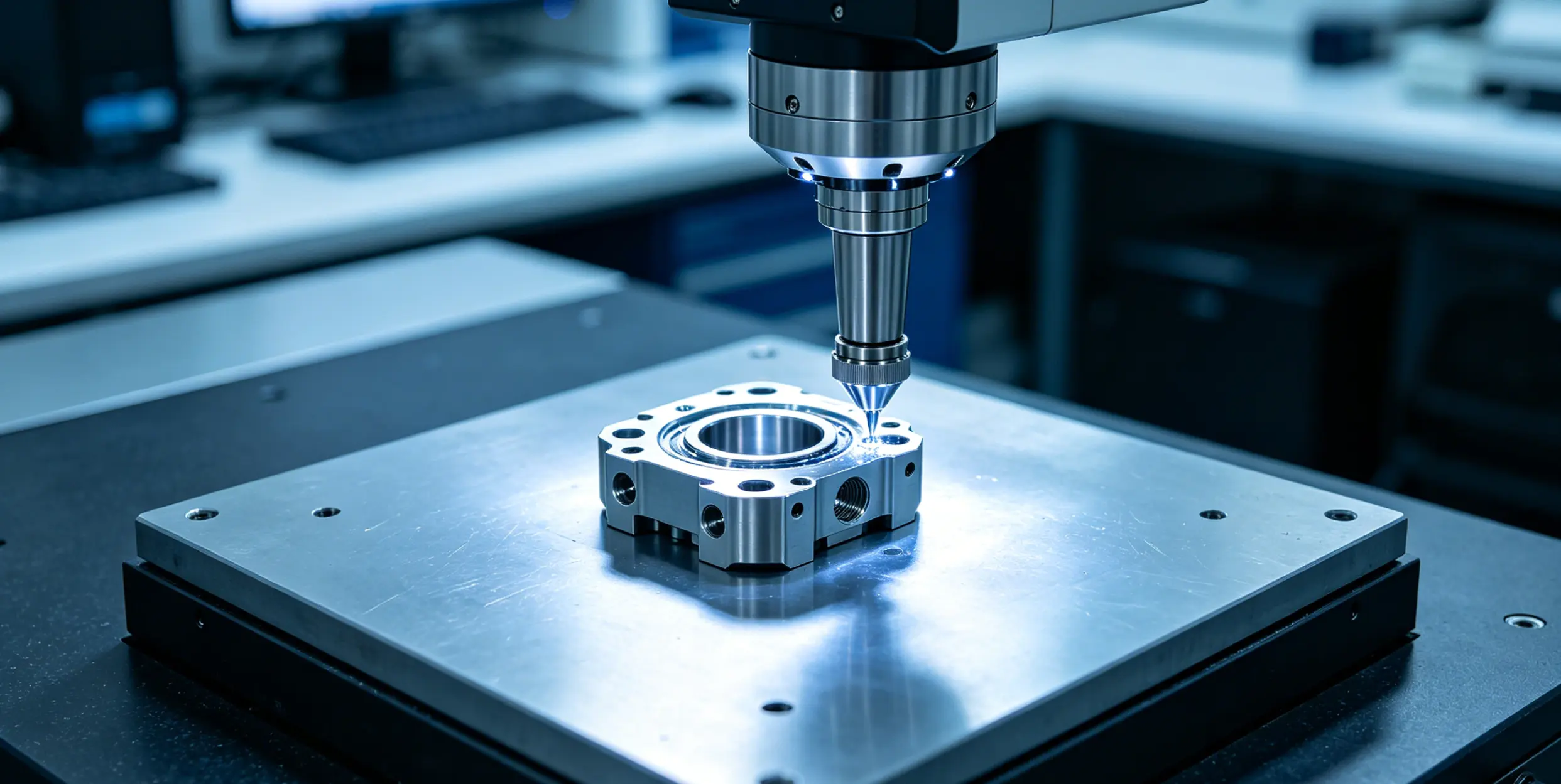
CNC machining uses computer-controlled machine tools to remove material from a workpiece, shaping it into a desired part. Unlike additive manufacturing (3D printing), it starts with more material than the final part, inherently generating waste in the form of chips. This is a key consideration, especially with expensive materials.

The Workflow: CAD to Component

1.  CAD Design: Create a 2D or 3D digital model.

2.  CAM Conversion: Translate the CAD model into machine instructions (G-code) using CAM software, defining toolpaths, speeds, and feeds.

3.  Machine Setup: Secure the workpiece and load the necessary cutting tools.

4.  Execution: Load the G-code into the CNC machine's controller (MCU), which directs the machine's axes and spindle to cut the part. G-code commands (like G00, G01, G02/G03) control movement, while M-codes handle auxiliary functions like spindle start/stop (M03/M05) and tool changes (M06).

Core CNC Operations

  •  Milling: Uses rotating multi-point tools (end mills) to remove material from a stationary workpiece. Creates slots, pockets, contours, and flat surfaces. Multi-axis (3, 4, 5-axis) machines handle complex geometries.
  •  Turning (Lathe): Rotates the workpiece against a stationary single-point tool to create cylindrical parts. Operations include facing, boring, threading, and tapering.
  •  Drilling: Creates cylindrical holes using rotating drill bits. Related operations include reaming (precision hole sizing) and tapping (internal threading).
  •  Routing: Similar to milling but often used for larger surface areas on softer materials like wood, plastics, and foam.
  •  Grinding: Uses abrasive wheels for high precision and smooth surface finishes, often a secondary operation.

Tooling Considerations

Tool selection is critical for precision, finish, speed, and cost. Common tools include end mills (flat, ball nose), face mills, drill bits, reamers, taps, and lathe tools. Tool materials range from High-Speed Steel (HSS) for general use to Carbide for harder materials and higher speeds, and Diamond/PCD for abrasive materials. Tool wear is an ongoing cost factor in CNC, unlike the non-contact nature of laser cutting.

Material Compatibility

CNC machining handles a vast range of materials :

  • Metals: Aluminum (highly machinable), Steel (various grades), Stainless Steel (harder to machine), Brass, Copper, Titanium (difficult, high tool wear), Magnesium.
  • Plastics: ABS, Nylon, Polycarbonate (PC), POM (Delrin), Acrylic (PMMA), PEEK, PVC, HDPE, PTFE.
  • Wood: Hardwoods, softwoods, plywood, MDF.
  • Composites: Carbon Fiber (CFRP), Fiberglass (abrasive, requires special tooling).
  • Foam: Machinable, but soft types can compress or tear.

Material properties like machinability (ease of cutting), hardness (resistance to tool penetration), thermal conductivity (heat dissipation), and ductility significantly impact the process, tool choice, speed, and cost.

Material Limitations

CNC struggles with:

  • Extremely Hard/Brittle Materials: Ceramics, Glass (fracture risk).
  • Very Soft/Flexible Materials: Rubbers, Silicones (deformation, poor accuracy).
  • Heat-Sensitive Materials: Many thermoplastics (melting, warping).
  • Highly Flammable Materials: Certain foams, paper products (safety hazard).
  • Difficult-to-Machine Alloys: Superalloys (Inconel), Titanium (rapid tool wear, high forces).
  • Abrasive Composites: CFRP, Fiberglass (extreme tool wear, delamination).

Precision and Tolerances

CNC is known for high precision.

  • Standard Tolerance: Typically ±0.005 inches (±0.127 mm). Plastics may have looser standard tolerances (±0.010 inches).
  • High-Precision Tolerance: Can reach ±0.0005 inches (±0.0127 mm) or better with specialized equipment/processes.
  • Surface Finish (Ra): Standard "as-machined" finish is often 63-125 µin Ra (1.6-3.2 µm Ra), showing tool marks. Finer finishes require slower speeds or secondary operations (grinding, polishing).
  • Cost Implication: Tighter tolerances and finer finishes significantly increase cost and lead time.

Geometric Capabilities and Limitations

CNC excels at creating complex 3D shapes, especially with multi-axis machines. However, limitations exist:

  • Tool Access: Difficulty machining deep, narrow cavities or features with high depth-to-width ratios (>3:1) due to tool deflection and chip evacuation issues.
  • Internal Features/Undercuts: Challenging or impossible with standard 3-axis machines; often require multi-axis setups or specialized tooling, increasing cost.
  • Sharp Internal Corners: Impossible with rotating cylindrical tools; always leave a fillet radius matching the tool radius. Achieving small radii requires small, fragile tools, increasing time/cost.
  • Thin Walls: Prone to vibration and deflection during machining (minimum recommended thickness often ~0.8mm for metals, ~1.5mm for plastics).

Industrial Applications

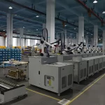
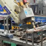
CNC machining is ubiquitous, used in:

  • Aerospace: Engine components, structural parts, landing gear.
  • Automotive: Engine blocks, transmission parts, molds.
  • Medical: Surgical instruments, implants, diagnostic equipment parts.
  • Electronics: Enclosures, heat sinks, connectors.
  • Defense: Firearms components, military vehicle parts.
  • Oil & Gas: Valves, pistons, drill bits.
  • Energy: Turbine components, Solar Panel mounts.
  • Tooling & Molds: Injection molds, dies, jigs, fixtures.
  • Rapid Prototyping: Functional prototypes from engineering materials.

Exploring Laser Cutting

The Thermal Separation Method

Laser cutting uses a focused, high-intensity laser beam to melt, burn, or vaporize material along a programmed path. It's a non-contact, thermal process guided by CNC. Key advantages include high precision, speed (especially on thin materials), intricate pattern capability, clean edges, and minimal force on the workpiece.

The Workflow: Beam Generation to Cut

  1. Laser Source: Generates the laser beam (e.g., CO2 gas mixture, fiber optic, Nd:YAG crystal).
  2. Beam Delivery: Transports the beam via mirrors (CO2) or optical fiber (Fiber) to the cutting head.
  3. Focusing Optics: A lens or mirror in the cutting head focuses the beam to a tiny spot, increasing power density.
  4. Assist Gas: A gas jet (oxygen, nitrogen, air) coaxial with the beam ejects molten material, cools the area, and protects the lens.
  5. Motion Control: CNC system moves the cutting head or workpiece to follow the design.

Material removal occurs via vaporization, melt and blow (fusion cutting), or reactive cutting (using oxygen).

Laser Types and Their Uses

  • CO2 Lasers (10.6 µm wavelength): Excellent for non-metals (wood, acrylics, plastics, fabrics, paper, leather) and thinner metals. Versatile but require more maintenance.
  • Fiber Lasers (~1.06 µm wavelength): Dominant for cutting metals (steel, aluminum, brass, copper), especially reflective ones. Highly efficient, fast, low maintenance, but higher initial cost.
  • Nd:YAG / Nd:YVO Lasers (~1.064 µm wavelength): Solid-state lasers used for metals, some plastics/ceramics. Good for pulsed operation (drilling, engraving). Less efficient and higher maintenance than fiber lasers.

Choice depends on material absorption at the laser's wavelength.

Role of Assist Gases

Assist gases (delivered via nozzle) are crucial for ejecting molten material, cooling, lens protection, and sometimes enhancing the cut.

  • Oxygen (O2): Reactive gas, used for carbon steels. Adds exothermic heat, allowing faster cutting of thicker steel but leaves an oxidized edge.
  • Nitrogen (N2): Inert gas, used for stainless steel, aluminum, etc., where oxidation is undesirable. Produces clean, bright edges but requires higher laser power/pressure.
  • Compressed Air: Lower-cost option for some steels, aluminum, plastics. Provides some speed benefit over nitrogen but results in some edge oxidation.

Material Compatibility

Laser cutting works on a wide range of sheet materials :

  • Metals: Steel, Stainless Steel, Aluminum, Copper, Brass, Titanium (Fiber lasers preferred).
  • Plastics: Acrylic (excellent results), POM, PETG. Others like ABS, PVC, thick PC are problematic. (CO2 lasers typical).
  • Wood: Hardwoods, Plywood, MDF (CO2 lasers typical, charring possible).
  • Fabrics/Textiles: Cotton, Leather, Polyester (Clean cuts, no fraying).
  • Others: Paper, Cardboard, Rubber, Foam (laser-safe types), Glass (etching mainly), Ceramics (specialized lasers).

Material properties like reflectivity (difficult for lasers, especially CO2), thermal conductivity (high conductivity requires more power), and thickness (limited by laser power) are key factors.

Material Limitations and Hazards

Certain materials are unsuitable or dangerous due to toxic fumes, flammability, or poor cut quality:

  • PVC (Vinyl, Pleather): Releases highly toxic and corrosive chlorine gas. Never cut.
  • ABS: Emits toxic cyanide gas; melts poorly.
  • Polycarbonate (Thick >1mm): Absorbs IR strongly, melts, discolors, catches fire.
  • HDPE: Melts, catches fire easily.
  • Polystyrene/Polypropylene Foam: Extremely flammable, toxic smoke.
  • Epoxy/Fiberglass Composites: Emit toxic fumes.
  • Coated Carbon Fiber: Noxious fumes.
  • Materials with Halogens (Chlorine, Fluorine): Includes PTFE (Teflon), many flame retardants.
  • Chromium-Tanned Leather: Toxic chromium fumes.

Always verify material composition and consult safety data sheets.

Precision, Kerf, and Edge Quality

  • Precision/Tolerance: Excellent for 2D patterns, typically ±0.10 mm (±0.004 inches) or better.
  • Kerf Width: Very narrow, typically <0.5 mm to 1.0 mm, allowing fine details and efficient nesting.
  • Edge Quality: Often smooth, clean, and square, minimizing post-processing. Potential issues include dross (metal), striations, charring (organics), or melting (plastics).
  • Heat Affected Zone (HAZ): An inherent characteristic due to the thermal process. Laser cutting produces a very narrow HAZ (typically <0.5 mm), minimizing impact on material properties near the cut.

Geometric Capabilities

Laser cutting excels at intricate 2D patterns and profiles from sheet materials. It can also perform surface engraving, etching, marking, and perforating. However, it is limited in creating true 3D shapes with significant depth variation or complex contours from solid blocks.

Industrial Applications

Laser cutting is widely used for processing sheet materials in:

  • Automotive: Body panels, Chassis parts, exhaust systems.
  • Aerospace: Lightweight components, engine parts, panel assemblies.
  • Medical: Surgical instruments, stents, implants, diagnostic equipment parts.
  • Electronics: PCBs, enclosures, connectors, heat sinks.
  • Construction/Architecture: Structural components, decorative metalwork, facades.
  • Jewelry: Intricate designs in precious metals.
  • Textiles/Fashion: Cutting patterns without fraying.
  • Signage: Letters, logos from acrylic, wood, metal.
  • General Fabrication: Custom sheet metal parts.

CNC Machining vs. Laser Cutting: Head-to-Head

Feature

CNC Machining (Subtractive)

Laser Cutting (Thermal Separation)

Process Type Mechanical removal via cutting tools Thermal removal via focused laser beam
Material Contact Contact Non-Contact
Primary Geometry 3D shapes, features with depth 2D profiles, intricate patterns, surface marking
Material Focus Bulk materials (Metals, Plastics, Wood, etc.) Sheet materials (Metals, Plastics, Wood, Fabric, etc.)
Key Material Factors Hardness, Machinability Reflectivity, Thermal Properties, Fumes, Thickness
Thickness Handling Excellent for thick sections Best for thin to medium sheets (power dependent)
Typical Tolerance ±0.005" (0.127 mm) standard (tighter possible) ±0.004" (0.1 mm) or better (2D features)
Surface Finish Shows tool marks; may need post-processing Often smooth, clean edges; minimal HAZ
Internal Corners Limited by tool radius (filleted) Sharp external corners possible
Cutting Speed Faster for bulk removal/thick materials Faster for thin materials/intricate 2D cuts
Setup Time Longer (tooling, fixturing) Shorter (no tool changes for geometry)
Consumables/Wear Cutting tools (wear), Coolant Assist gases, Nozzles, Optics (maintenance)
Material Waste Chips (can be significant) Minimal (narrow kerf, good nesting)
Cost: Prototype Higher for simple parts Often lower for simple 2D parts
Cost: High Volume Often more cost-effective per part (esp. 3D) Competitive for high-speed sheet cutting
Key Advantages 3D capability, thick materials, material strength Speed (thin), 2D intricacy, clean edges, non-contact
Key Limitations Tool access, internal corners, setup time, chips Thickness limits, HAZ, fume hazards, reflectivity, 2D


Making the Right Choice: Key Decision Factors

Selecting the best process requires evaluating your project against these factors:

  1. Material & Thickness: Is it bulk or sheet? Hard, reflective, or prone to fumes? Thick or thin?
  2. Geometry: Primarily 2D or 3D? Intricate details, internal features, or depth variations?
  3. Precision & Tolerance: What level of accuracy is needed? Is HAZ acceptable?
  4. Surface Finish: Are tool marks acceptable? Is a clean edge critical?
  5. Volume & Budget: Prototype, low-volume, or high-volume? Cost constraints?
  6.  Turnaround Time: Is speed a major factor?

Choose CNC Machining When:

  • Working with thick materials.
  • Creating complex 3D shapes with depth, contours, pockets, threads.
  • Material is unsuitable for laser (e.g., PVC, highly reflective without fiber laser).
  • High structural integrity from solid block is needed.
  • Tight 3D tolerances are critical, and HAZ is unacceptable.

Choose Laser Cutting When:

  • Working with thin to medium-thickness sheet materials.
  • Design involves intricate 2D patterns or fine details.
  • Speed and rapid turnaround are priorities.
  • A clean, smooth edge is needed directly off the machine.
  • Material is delicate (benefits from non-contact process).
  • Cost-effective prototyping/low-volume of suitable 2D parts is needed.

Consider hybrid approaches where laser cutting creates the initial profile, and CNC adds 3D features.

Conclusion

CNC machining and laser cutting are indispensable manufacturing tools, but suited for different tasks. CNC machining's strength lies in its subtractive power to create complex 3D parts from bulk, often thick, materials with high precision. Laser cutting excels with its thermal, non-contact approach, offering unparalleled speed and intricacy for 2D patterns in sheet materials, often yielding clean edges directly.

The optimal choice depends entirely on your project's specific needs regarding material, thickness, geometry (2D vs. 3D), precision, finish, volume, budget, and required turnaround time. Carefully evaluating these factors against the distinct capabilities and limitations of each process will lead to the most efficient and effective manufacturing solution.

Related Information
Life Science Equipment R&D: How Does Concurrent Design Optimize Component Manufacturability?

Concurrent design optimizes component manufacturability early in R&D through cross-departmental collaboration, significantly improving the production efficiency and flexibility of life science equipment. Combining modular design with virtual simulation effectively reduces development costs, shortens product time-to-market, and enhances market competitiveness.

What Is Riveting? A Comprehensive Guide to the Process and Its Applications

Riveting is a well-established method of joining two or more pieces of material together, most commonly metals, using a mechanical fastener known as a rivet. This technique has been used for centuries and remains essential in various industries, such as aerospace, automotive, construction, and shipbuilding. Despite the rise of alternative fastening methods, riveting continues to be an invaluable solution for applications where strong, durable, and vibration-resistant joints are required.

The Difference Between Pickling and Passivation: Key Factors to Consider in Metal Cleaning

Pickling and passivation are two essential processes used to treat metal surfaces, particularly stainless steel, to improve their resistance to corrosion. While both techniques help maintain the integrity and lifespan of metal components, they differ significantly in their methods, applications, and the results they achieve. Whether it’s ensuring the durability of machinery in harsh environments, enhancing the aesthetics of a product, or complying with industry standards, understanding these processes is critical for industries such as aerospace, pharmaceuticals, food processing, and chemical manufacturing.

5 Benefits of Using Sheet Metal Fabrication in the Medical Industry

The medical industry demands not only precision and durability but also compliance with stringent safety and hygiene standards. One material that consistently meets these requirements is sheet metal. From MRI machine frames and surgical tables to portable medical devices and diagnostic equipment, sheet metal is essential for manufacturing components that ensure the longevity, functionality, and safety of medical tools and devices.

Email to this supplier

Name:
Phone:
Email:
Message: