






Send Message
Privacy statement: Your privacy is very important to Us. Our company promises not to disclose your personal information to any external company with out your explicit permission.


Sheet metal bending is a critical manufacturing process used to produce brackets, enclosures, panels, housings, frames, chassis, and structural components. Modern CNC bending technology provides excellent repeatability and dimensional consistency, making it suitable for rapid prototypes, small-batch production, and high-volume manufacturing.
However, even advanced CNC equipment cannot fully compensate for a design that is difficult to manufacture.
This is why Design for Manufacturing (DFM) is essential for sheet metal components. A DFM-focused design considers material properties, bend radius, flange dimensions, hole placement, tolerances, tooling access, and bend sequence before production begins.
For companies using CNC sheet metal bending services, applying DFM principles early can reduce manufacturing problems, shorten production time, control costs, and improve final part quality.
This article covers the most common sheet metal bending mistakes and practical ways to avoid them.
Design for Manufacturing, or DFM, means designing a component according to the capabilities and limitations of its manufacturing process.
For CNC sheet metal bending, important DFM factors include:
The goal is not simply to create a CAD model that meets functional requirements. The goal is to create a design that can be manufactured accurately, consistently, and economically.
One of the most common mistakes is designing a bend radius that is too small for the selected material and thickness.
During bending, the outside of the material is stretched while the inside is compressed. An excessively small radius can create high levels of stress and may result in cracking, particularly with harder materials or certain aluminum and stainless steel grades.
Do not automatically choose the smallest possible bend radius. Select a practical radius based on the material, thickness, tooling, and required bend angle.
An appropriate bend radius can improve reliability and reduce the risk of cracking.
Holes, slots, and cutouts located too close to a bend can become distorted during forming.
Material movement around the bend may elongate or deform the opening, causing problems during assembly with screws, pins, fasteners, or mating components.
Maintain sufficient distance between holes and bend lines. The appropriate distance depends on material thickness, bend radius, tooling, and feature size.
For critical components, increasing the distance provides a larger manufacturing margin.
A flange must provide enough material for the selected punch and die to form the bend correctly.
If a flange is too short, the tooling may not be able to properly engage the material. This can cause inconsistent angles, incomplete bends, or tool interference.
Check minimum flange dimensions against the intended press brake tooling before finalizing the design.
This is particularly important for small brackets, narrow tabs, and compact enclosures.
When a bend terminates near an edge or another bend, insufficient relief can cause unwanted deformation, tearing, or material buildup.
Bend relief is especially important for parts with multiple adjacent flanges or complex corners.
Add appropriate bend reliefs where required to control material deformation. The size and geometry of the relief should be selected according to material thickness and part geometry.
A part may appear manufacturable in CAD but become difficult to produce because one bend blocks access to another.
Previously formed flanges can interfere with the press brake tooling or machine structure. This is especially common with deep boxes, enclosures, and multi-bend assemblies.
Consider the complete bending sequence before production.
Manufacturers may need to determine:
A practical bend sequence can significantly improve production efficiency.
Every additional bend increases processing time, setup requirements, and opportunities for dimensional variation.
A complicated design is not necessarily a better design.
Review every bend and determine whether it provides a necessary structural, functional, or assembly benefit.
If two designs provide similar performance, the one requiring fewer operations is often more economical to manufacture.
This becomes especially important in high-volume production.
CNC bending provides high repeatability, but sheet metal is still a flexible material whose behavior is influenced by material strength, thickness variation, grain direction, springback, tooling, and process conditions.
Specifying extremely tight tolerances on every dimension can increase manufacturing and inspection costs without improving product performance.
Apply tighter tolerances only to dimensions that are functionally critical.
Separate critical dimensions from general dimensions and use realistic tolerances for each. This helps balance precision, manufacturability, and cost.
After bending, sheet metal tends to partially return toward its original shape. This phenomenon is known as springback.
The amount of springback varies according to material type, thickness, strength, bend radius, and bending method. High-strength steels and some stainless steels can present greater springback challenges.
Account for springback when establishing bend angles and tolerances.
Experienced CNC bending manufacturers can compensate through tooling selection, machine settings, and process parameters. For critical components, prototype testing can help validate the final geometry.
The direction of the material grain can influence bending performance.
For certain materials and bend geometries, bending in an unfavorable grain direction can increase the possibility of cracking, particularly when combined with a small bend radius.
Consider grain direction when designing critical bends and communicate material requirements to your manufacturing partner.
For demanding applications, the manufacturer can recommend an appropriate material orientation and bending strategy.
Small holes, slots, notches, and cutouts positioned too close to an edge can weaken the remaining material and may deform during cutting or bending.
Narrow strips of material between adjacent features can also create instability during manufacturing.
Maintain sufficient material around holes and cutouts, and avoid unnecessarily narrow sections whenever possible.
A small geometry adjustment during the design stage can prevent significant production problems later.
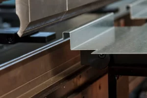
Whenever possible, standardize material thickness across a project. Different thicknesses may require different tooling, machine settings, and setups.
Using common material specifications can simplify production and reduce manufacturing costs.
Standard punches and dies are generally more economical than custom tooling.
When practical, designing components to work with commonly available CNC press brake tooling can reduce setup time and production costs.
Many sheet metal parts require powder coating, anodizing, plating, painting, or brushing after bending.
Designers should consider how bending operations and tooling may affect cosmetic surfaces. Critical visible areas may require special handling or finishing specifications.
A manufacturable sheet metal design should aim to minimize unnecessary cutting, bending, repositioning, and inspection operations.
Reducing the number of manufacturing steps can improve both production efficiency and consistency.
Before sending a CAD file to a manufacturer, review the following:
DFM becomes increasingly important as production volume grows.
For prototypes, the focus may be on validating geometry and function. For small batches, reducing setup time and manufacturing operations can help control unit costs.
For high-volume orders, even a small production inefficiency can become significant when multiplied across thousands of parts.
Optimizing bend sequences, tooling, tolerances, and material utilization from the beginning helps create a design that can efficiently transition from rapid prototyping to small-batch and high-volume production.
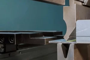
Successful CNC bending starts with a manufacturable design.
Problems such as excessively small bend radii, short flanges, misplaced holes, inadequate bend relief, unrealistic tolerances, and poor bend sequences can all increase production costs or compromise part quality.
The best approach is to consider manufacturing requirements from the beginning.
By applying DFM principles and working with an experienced CNC sheet metal bending services provider, engineers can reduce manufacturing risks, improve dimensional consistency, shorten production lead times, and create sheet metal components that are easier to produce at prototype, small-batch, and high-volume scales.
Design smarter. Bend better. Manufacture with confidence.
Learn how CNC machining tolerances impact automotive component accuracy and reliability, including standards, key factors, and precision manufacturing solutions.
Discover how precision machining supports HPP equipment manufacturing with high-quality custom metal parts, CNC machining, and sheet metal fabrication solutions.
Discover how laser cutting technology helps automotive manufacturers reduce hot forming costs while achieving superior laser cutting accuracy and meeting laser cutting tolerance standards. Learn how precision sheet metal fabrication improves quality, productivity, and profitability.
Discover how CNC tube bending services improve precision sheet metal processing for automotive, medical, aerospace, and industrial applications. Learn the advantages of CNC bending, CNC sheet metal bending, materials, manufacturing processes, and how custom fabrication ensures superior quality and cost efficiency.
Email to this supplier
Author:
Ms. CTT TECHNOLOGY (UK) LIMITED
E-mail:
Phone/WhatsApp:

Privacy statement: Your privacy is very important to Us. Our company promises not to disclose your personal information to any external company with out your explicit permission.